Mobile Robot Servosila "Engineer"
The mobile robot is designed for applications where an environment or a nature of engineering operations pose a risk to human life:
- Disaster Response,
- Firefighting,
- Search and Rescue,
- Industrial Engineering and Maintenance and
- Maintenance of Tunnels and Pipelines.
The robot is also used as a Research and Education platform.
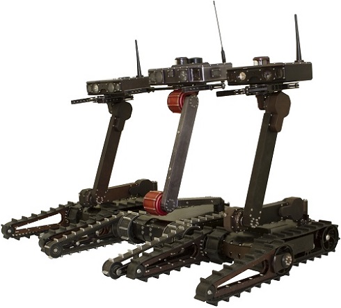
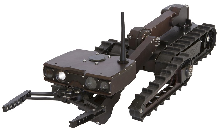
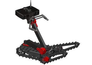
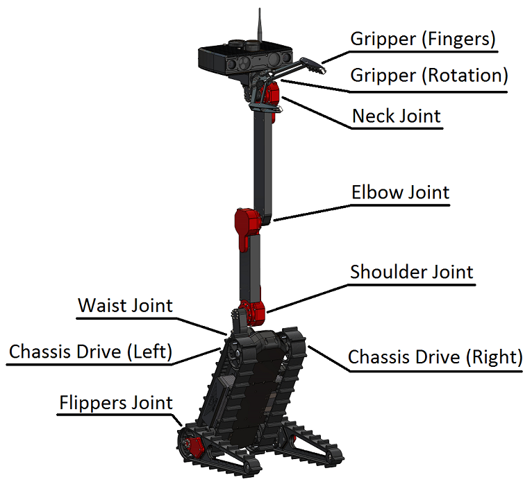
The robot has a modular construction which simplifies its maintenance and reduces the cost of ownership throughout its service life. It features multiple degrees of freedom depending on a chosen configuration. Its robotic arm is capable of lifting loads and reaching substantial heights. The robot has a durable, but light-weight metal body, hardened electronics and a sensors package, capable of withstanding the stresses and rough treatment.
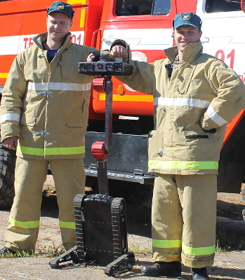
Lightweight Robot Transportable in a Backpack
The robot is designed to have as small weight and footprint as possible while still meeting the requirements of being able to climb stairs and raise the sensor head high enough to look inside parked cars. The robot fits inside a regular backpack and can be simply carried to a mission area by its human operator. Backpack transportability is a required feature when it comes to using the robots in hard-to-access areas where transportation by cars or trucks is impossible.
Simple to Use
The mobile robot is rugged, simple to use, does not require much expertise or heavy training for successful application. The robot is controlled via a virtual reality glasses and a joystick. The virtual reality glasses display video streams coming out of the video cameras installed in the sensor head of the robot. The joystick is used to control the motion of the robot including its gripper. It takes half an hour for an average person to fully master control of the robot. 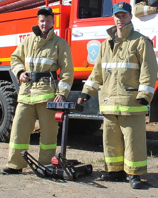
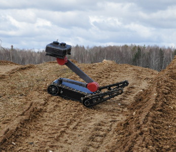
A Heavy Duty Machine
The robot is designed for outdoor use. The robot is watertight, capable of operation in the rain, dust and snow.
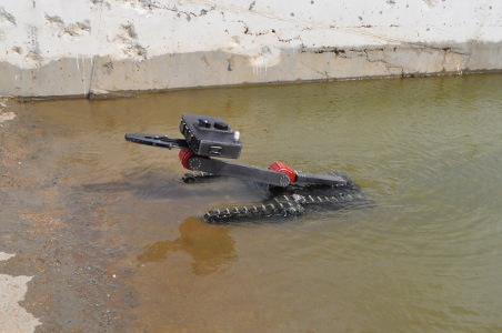
Stairs Climbing
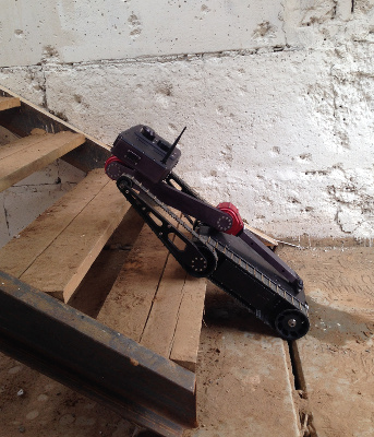
A tracked chassis of the mobile robot is specifically designed for climbing stairs of high-rise buildings in industrial, urban and rural environments. Remote visual inspection of high-rise buildings is a key mission scenario.
The small size of the robot enables it to easily traverse doorways and narrow passages either inside damaged buildings or outdoors while carrying a powerful array of sensors and tools.
A pair of auxiliary flipper threads helps the mobile robot climb stairs and negotiate obstacles in industrial, urban and rural environments.
Self-Leveling
The mobile robot is capable of leveling itself from sideways or upside down positions. This capability greatly improves operational persistency of the robot in a target area of operations. The robot can seamlessly recover from mistakes made by its human operator thus increasing the chances of success.
Robotic Arm Manipulator
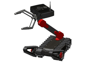
The robot is equipped with a robotic arm which enables the robot to perform dirty or potentially dangerous engineering operations remotely. The arm is capable of lifting heavy loads off the ground for carrying them for inspection in a safe location. The arm is a flexible remotely-controlled tool that can grasp, push or pull objects. Door opening is an important task performed by the robotic arm. The robot is capable of opening different doors either by employing the gripper of the arm, or by using special tools.
The arm is made of servo joints and rigid segments that connect them. The more joints are included into the configuration, the more degrees of freedom the arm obtains, and the more of a flexible tool the arm becomes.
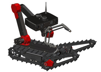
A two-segment arm allows the robot to reach out much further away from the chassis, or much higher up, and enables applications such as visual automobile inspection, and handling of potentially explosive objects. Such a two-segment arm comes with either two servo joints or with three servo joints. Both of the arm configurations enable a very flexible remote object manipulation, while the arm with three-servo joints has some advantages in confined areas where the chassis motion is restricted, such as tunnels or cellars.
A one-segment arm significantly increases mission capabilities of the robot. Such a robot can raise its sensor head, and use a gripper to grab objects from the ground or tabletop. A single segment arm can come with one servo actuator joint, or with two servo actuator joints. A single-segment-arm configuration can be enhanced by adding a gripper, or a rotating gripper. The rotating gripper allows the robot to rotate door handles to open doors in buildings. The gripper enables robots in such a configuration to perform many kinds of disaster response or public safety missions including removal of dangerous objects from populated areas.
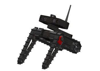
In the simplest case, there is no arm at all, and the robotic head is mounted directly on the top of the turret servo mechanism. A non-actuated rigid extender neck is needed to move the center of gravity towards the middle of the robot. This kind of lightweight but very capable configuration is designed for reconnaissance or visual inspection missions, or for carrying mission payloads that do not require a robotic arm for operation. It is worth noting that a gripper can be added to this configuration as well, primarily for delivering and dropping of objects at desired locations.
Grippers and other Tools
The mobile robot can be equipped with a rotating or a regular gripper that can capture and carry objects. The grippers are used to manipulate objects while performing engineering operations or visual inspection missions. Additional tools such as a drill or a circular saw can be installed either in place of the gripper, or on the gripper itself.
Choose a rotating gripper over a regular gripper, if a mission profile calls for opening doors by rotating door handles, or if an extra degree of freedom of the gripper is required for precise object manipulation. The gripper can also be excluded from the configuration, if the arm of the robot is to be used for carrying mission-specific payloads, for example, flame-retardant grenades or ground- or wall-penetrating radars, rather than for object manipulation.
The fingers of the gripper come with hardpoints for connecting external tools. The hardpoints on the fingers and on the chassis come handy when the robot needs to be adapted for a specific remote engineering operation. For example, special claws at the tips of the fingers of the gripper enable the robot to drag suspicious objects such as left bags, cut open holes, or gently open the bags. The claws also enable the robot to dig dirt or pick objects hidden under piles of rubbish. The claws are optional and field-installable.
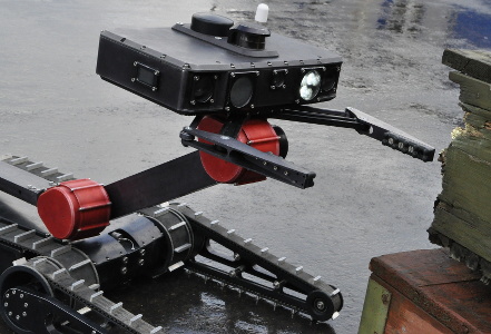
Robotic Head
A robotic head houses a mission control computer of the robot, a sensor package, and a radio communication module. The mission control computer comes as either a regular computer or a computer with a GPGPU-capable processor that enables massively parallel computations using OpenCL technology. The massively parallel computer is required if a high degree of autonomy of the robot is one of the mission profile requirements.
The robotic head can be installed directly on the turret servo of the robot chassis, or mounted on the top of a multi-segment robotic arm manipulator. A robotic gripper can be also mounted below the robotic head.
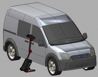
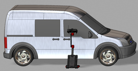
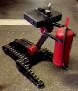
The mobile robot is designed with visual inspection application in mind. The robot is capable of raising its sensor head high enough to look inside automobiles with high ground clearance or into windows of buildings. The robot uniquely combines back-pack transportability and stairs climbing with a capability to look inside and under parked cars. This combination of capabilities is a key enabler for various public safety applications.
Sensors and Accessories
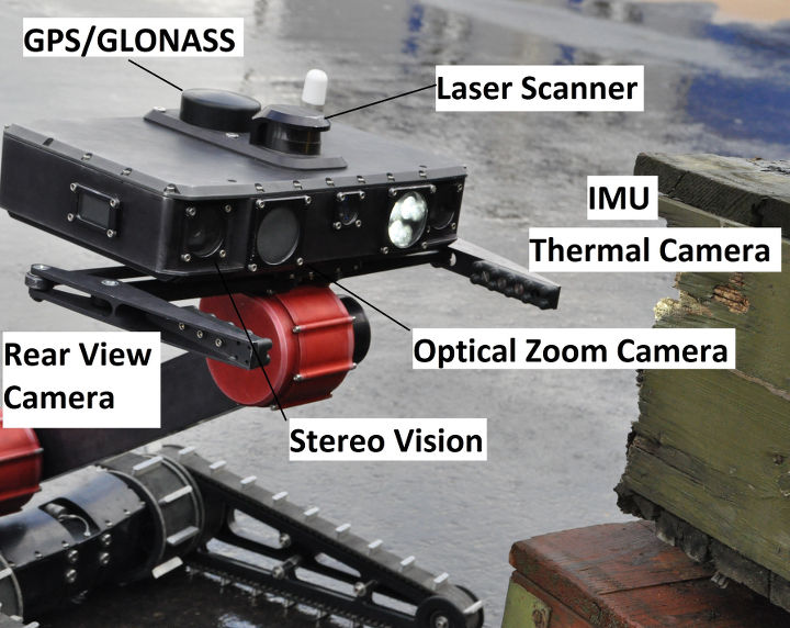
The following sensors and accessories can be installed in the robotic head, or mounted on the top of the robotic head:
- a wide-angle of view forward-, and rear-view cameras,
- an optical zoom camera,
- a thermal vision camera,
- a laser scanner,
- a GPS/GLONASS receiver,
- an inertial sensors unit (or IMU),
- a pair of cameras for stereo vision,
- and a headlight.
A rear view camera greatly improves situational awareness of the operator by acting as an equivalent of a rear view mirror in a car, and simplifies reverse driving. An operator of the robot can quickly switch between the cameras by pressing a button on the joystick.
Sensors such as the optical zoom camera, the thermal vision camera, and the headlight greatly improve visual inspection capabilities and situational awareness of the operator in challenging environments. The thermal vision camera enables several kinds of search-and-rescue, and firefighting missions.
The laser scanner acts as a short-range radar, and helps the robot detect and avoid obstacles. The laser scanner also enables 3D scanning, and automatic creation of detailed maps of the environments, including floor plans.
The laser scanner, GPS receiver, IMU and stereo vision cameras are key enablers for autonomy of the robot. Those sensors are required if a mission profile calls for a wider autonomy of the robot.
Radio Communications
The robot is remotely controlled via a duplex radio modem link, via WIFI or via a cable.
If the robot is to be used in outdoor environments such as for disaster response missions, then the radio modem option is the only suitable option for the radio communications package. There are several radio frequency options available. The choice of the frequency depends on the regulations of the country where the robot is to be used.
WIFI is a low-cost option for robots intended for use in laboratories, offices or campuses, primarily in academia.
Stereovision and 3D Laser Scanning
The mobile robot is equipped with a laser scanner which is used by the robot to detect obstacles while driving, and potentially perform 3D scanning of objects or indoor environments. The robot is also equipped with a stereovision system that complements the laser scanner. The devices enable the robot with simultaneous localization and mapping (SLAM) capabilities, improve 3D gripper control and enhance situational awareness of both the mobile robot in an autonomous operation mode and its human operator.
Automatic Obstacle Avoidance in Operator-Assisted Driving Mode
The mobile robot uses its laser scanner and stereo vision system to detect obstacles and automatically correct its trajectory to avoid hitting them. This feature significantly reduces the stress levels of an operator of the robot and increases the chances of successful mission completion in complex environments.
Field-Replaceable Batteries
The main battery of the mobile robot can be easily and quickly replaced in the field without any tools. Swapping the battery takes less than a minute. This feature ensures a continuous operation of the mobile robot in field environments via rotating a set of spare rechargeable batteries. The main battery is custom made to fit the chassis.
Operator Control Unit (OCU)
The robot is controlled by a single operator. Virtual reality goggles or a portable screen provide the operator with a clear picture from wherever the robot is; a joystick enables the operator to control the motion of the robot and its arm. It usually takes much less than a day for a new operator to fully master the process.
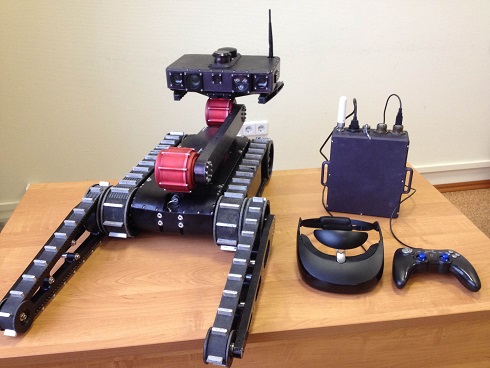
A portable operator control unit, or OCU, is specifically designed for controlling the robot in outdoor environments such as in disaster-struck areas. The unit is a passively cooled computer with a radio modem and a battery included into a water-tight enclosure.
The unit comes with ports for a joystick and either a virtual reality goggles or a portable handheld display. Please note that in order to use the OCU, the robot must be equipped with a radio modem.
Hardpoints and Bus Connectors for External Payload Integration
The robot is designed to be easily adaptable for ad-hoc missions via fast installation of tools and payload modules. There are multiple hardpoints and bus connectors throughout the body of the robot intended for fast installation of external payload modules.
The chassis, robotic head and robotic gripper have hardpoints and sockets for connecting external payload modules, such as gas analyzers, ground penetrating radars, infrared cameras, drills, and so on. The sockets connect the external payload modules to an onboard power supply, onboard Ethernet bus and an onboard CAN bus to facilitate remote control of the tools by a human operator through the OCU.
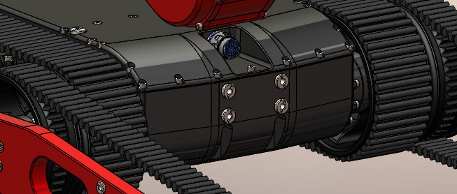
Robotic Chassis
The chassis of the robot is optimized for negotiating typical obstacles found in industrial and urban environments struck by a disaster.
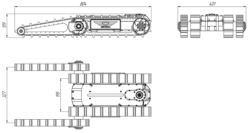
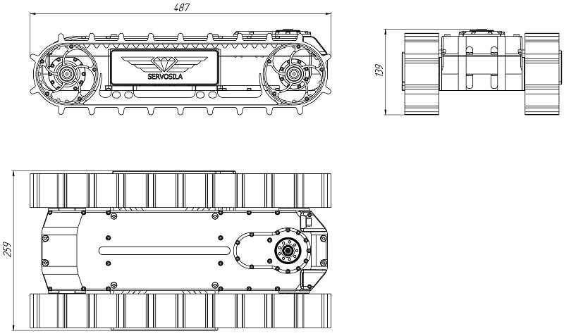
The chassis houses a drive motor assembly and a battery that powers the robot. The two key configuration options are a flipper threads or "flippers", and a turret servo. The flipper threads extend the length of the chassis which is needed when climbing stairs, or negotiating a terrain. The flippers are also used to lift the chassis off the ground to extend the reach of payloads. You may choose to include or not to include the flippers into configuration of your robot. Include the flippers if you want your robot to climb stairs. Exclude the flippers if the robot will be used as a carrier platform for payloads that do not require stairs climbing or when the weight of the robot needs to be reduced to a minimum.
The other choice to make is whether or not to add a turret servo to your robots chassis. The turret servo is a rotating hard point used for mounting various payloads on the chassis such as a robotic arm, a robotic head, a scanner, or a directional antenna. The turret servo can only be excluded if the chassis is to be used as a standalone platform; otherwise, it must be included into the configuration since it provides an important degree of freedom for the robotic arm and the sensor head of the robot.
Download a CAD model (*.STEP) "Chassis with Flipper Threads"
Download a CAD model (*.STEP ) "Chassis without Flipper Threads"
Specifications: Servosila "Engineer"
| Parameter | Value |
|---|---|
| Weight of the mobile robot | 13-25kg depending on the chosen configuration |
| Weight of the remote control station | 4.9kg |
| Max height reached by the sensor head | 130cm |
| Max speed | 5km/h |
| Gripper lifting capacity | Up to 6kg |
| Duration of a single charge operation - in continuous motion |
>4hrs depending on the type and intensity of the motion |
| - in a static surveillance mode | Up to 20hrs depending on surveillance payload selection |
| Max height of stairs steps | 23cm |
| Max angle of inclination of stairs | Up to 35deg depending on the material of the stairs |
| Protection rating | IP68 Dust-proof Watertight |
| Environmental temperature range | -20С … +40C with possible limitations due to specific payloads. optional: extended temperature range |
| Range of remote control, - line of sight |
several kilometers |
| - indoors or in urban environments | within a few hundred meters |
| Radio frequency | 902-928 MHz or 2.4 GHz |
| Laser scanner range | 4.5 m |
| Video cameras |
|
| Sensors for Automatic Navigation and Mapping |
|
| Optical zoom | x24 |
| Headlight | High-intensity white headlight with a visible spectrum |
| Battery system | LiFePo4, in a watertight casing, field-replaceable without tools |
| Number of hardpoints for external payloads | 4 |
| Onboard buses for connecting external payloads | CAN Ethernet USB |
Configuration Guide
The robots Servosila "Engineer" come in many different configurations that meet requirements of various mission profiles. The following components are configured individually:
- Step 1: Configure the Chassis
- Step 2: Configure the Robotic Arm
- Step 3: Configure the Robotic Head
- Step 4: Configure the Radio Communications Package, and OCU
- Step 5: Configure a Sensors Package