Servosila Servo Drives
 IN STOCK
 IN STOCK
 IN STOCK
 IN STOCK
Download
SC-60 Datasheet [PDF],
SC-25 Datasheet [PDF],
SC-series Device Reference [PDF],
CANopen Electronic Datasheet [EDS],
SC-series Programming Guide [PDF],
SC-series C++ Sample Projects [ZIP],
CAD files for SC-60R, and
CAD files for SC-60C,
CAD files for SC-25R, and
CAD files for SC-25C,
SC-25 Product Brochure [PDF],
...more.
Servosila SC-series Servo Drives & Brushless Motor Controllers are miniature electronic control units that provide high-precision control over a wide range of mechanisms actuated by electric motors (PMSM, BLDC, Direct Drive, Gimbal, Brushed) of any manufacturer. The controllers turn the motors into computer-controlled traction drives, high-precision direct drives,
or servo actuators when (optionally) paired with absolute position encoders (BISS-C, SSI, SPI, PWM or Quadrature) of any manufacturer
(e.g. RLS,
AMS,
CUI Devices,
etc).
Up to 45A of phase-to-phase current, and up to 32bits of angular precision are provided. The electronic units feature a microprocessor chip, a set of absolute encoder interfaces for shaft position measurements, a firmware implementation of advanced motion control algorithms that operate in a closed loop fashion, as well as CAN/CANopen, USB 2.0 and RC PWM interfaces for receiving commands from a control computer/PLC and sending back telemetry.
The brushless motor controllers are extensively used in various products of Servosila including its lines of robotic arms, and servo actuators. The controllers’ design incorporate multiple lessons learned by Servosila while operating its robots in various environments.
 IN STOCK
 IN STOCK
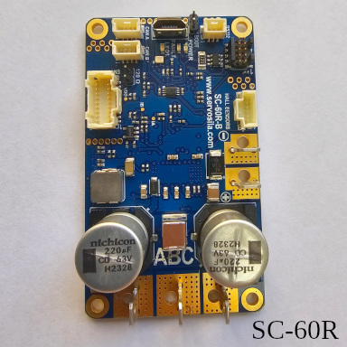
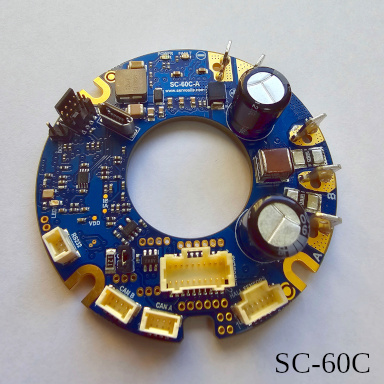
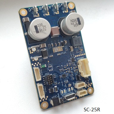
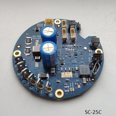
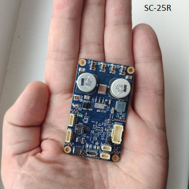
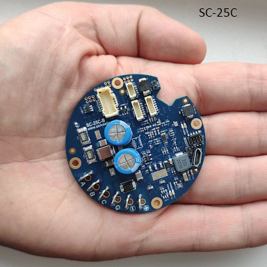
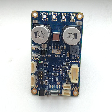
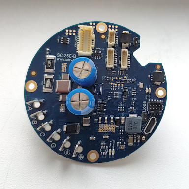
Servosila SC-series controllers come in two distinct forms, a rectangular one (SC-60R and SC-25R) and a circular one (SC-60C or SC-25C). The models are identical in terms of features and firmware. The models differ in their shapes and supported nominal motor currents only. Industrial designers might prefer one model over the other depending on what actuated mechanisms they are working on. At the same time, both electrical and software engineers rest assured that whichever model is chosen for a particular design, a full electrical and software compatibility is still in place.
Typical applications of Servosila SC-series controllers include:
- servo actuators, servo mechanisms,
- traction electric drives, thrust drives,
- industrial machines, pumps, conveyor belts,
- robots,
- robotic warehouses, robotic stores,
- starter-generators for internal combustion enginers,
- medical equipment and machines,
- farming and agricultural machines,
- test equipment, test beds,
- automated measurement and diagnostics equipment,
- CNC machines,
- astronomy, telescope mounts,
- actuated computer vision systems.
The controllers support the following kinds of electric motors:
- Brushless DC motors (PMSM, BLDC, Direct Drive, Gimbal) of any manufacturer,
- ... Sensored or Sensorless,
- ...with or without absolute shaft encoders,
- ...with or without a gearbox,
- ...with sinusoidal or trapezoidal control,
- as well as Brushed DC Motors
- and Solenoids.
The following interfaces to absolute position encoders are supported by the controllers:
- BISS-C encoder interface (e.g. RLS magnetic encoders),
- SSI encoder interface,
- SPI encoder interface (e.g. CUI Devices’ encoders),
- PWM encoder interface (e.g. AMS encoders),
- Quadrature interface
External absolute position encoders (optional) enable such functions as servo control, direct drive control, robust speed control at low speeds, a brake function, and various safety functions. If an electric drive does not have an encoder, the controllers are capable of operating using Hall sensors, or in an open loop position control mode similar to step motors.
A Sensorless control mode is available for controlling brushless motors that do not have built-in Hall Sensors or attached encoders.
The way the controllers are designed is that if an encoder is present, the system will try to use it whenever it makes sense. If no encoder is present, the system will still operate properly, but may do so not as good as it would with an encoder.
 IN STOCK
 IN STOCK
The controllers come with pre-soldered connectors (Molex & TE Connectivity) for attaching phase lines, power lines, sensors, encoders, and information buses. Besides the connectors, the electronic units come with soldering holes for every signal or power line; the holes allow cables to be soldered directly to the boards to form vibration-resistant connections.
The connectors are intentionally placed on the front side of the boards only. There are no connectors on the back side of the boards. The back side is intended for installation of a heat sink, or for attaching the boards directly to an enclosure designed to act as a heat sink.
All the connectors are facing upwards, perpendicular to the boards. None of the connectors are facing sideways. This arrangement simplifies cable routing within cramped spaces such as cylindrical enclosures of servo actuators or mobile chassis.
The SC-series controllers feature two CAN bus ports (parallel). This simplifies cabling of multiple controllers into a chain, for example, inside a robotic arm manipulator or a robotic chassis, and streamlines in-the-field repair or replacement process.
All controllers have an on-board terminal 120 Ohm resistor prescribed by the CAN bus standard. The resistor can be turned on or off via a jumper. Only one controller in a chain needs to have the terminal resistor enabled.
There is a way to upgrade the controllers’ firmware via a RS232 port, including field firmware upgrades of servo actuators or mobile vehicles.
Operation Modes & Capabilities
Servosila SC-series Brushless/Brushed Motor Controllers are capable of controlling motors in several different ways called “modes”. The controllers switch from one mode to another upon receiving commands sent via CAN, USB 2.0 or RC PWM by a control computer/PLC.
- “Torque Control”. In this mode, the system tightly controls a prescribed electrical current flowing through the motor. This defines torque with which a brushless/brushed motor actuates its payload. This mode would typically be employed whenever what matters is torque rather than speed of the motor, for example, in a test/diagnostics equipment, or in a highly dynamic walking robot application.
- “Electronic Speed Control (ESC)”. In this mode, the SERVOSILA controllers maintain a constant commanded speed of rotation of the motors’ shafts under an influence of varying external forces. The controllers automatically increase or decrease torque in response to perturbations of external loads thus keeping the speed of the drive constant. This mode is often used when actuating pumps, conveyor belts, thrust drives, mobile chassis, and in many other applications.
- “Servo Control”. In this mode, the controller turns a brushless or a brushed motor into a servo motor capable of holding a commanded position (with or without a gearbox). Upon receiving a servo command, the controller first moves the drive’s output shaft to a specific commanded position (angle), and then holds the position under an influence of external forces that try to disturb the balance. An encoder is required in this mode to measure absolute position of the drive’s output shaft. The encoder can be connected to the controller via one of available encoder interfaces (BISS-C, SSI, SPI, PWM, Quadrature). Up to 32bit of angular precision is supported. The servo control mode is widely used in applications ranging from servo actuators of robotic arm manipulators, to CNC machines, to robotic warehouse systems.
- “Direct Drive”. In this mode the controller directly positions magnetic fields inside a brushless motor, and achieves the highest possible precision of positioning accuracy. This mode is often used with electric drives that do not have a gearbox (thus the name). Typical applications include computer vision systems, CNC machines, linear motor actuators, - all those applications where use of a gearbox is avoided to minimize backlash-related issues that affect positioning accuracy. A brushless motor operated in a direct drive mode is much better than a more traditional stepper motor.
- “Brake”. The controllers implement an energy-efficient “parking brake” mechanism that blocks a brushless motor’s motion. This is achieved without a need for an external braking mechanism. In this mode the controller monitors position of a brushless motor’s rotor using either Hall sensors or an encoder, and makes energy-efficient adjustments to the magnetic field inside the motor in such a way that rotation of the output shaft is blocked. The built-in braking mechanism comes handy in applications where motion may need to be stopped and then put on a brake, - such as a conveyor belt or a mobile chassis. Imagine a mobile robot that has to stop while climbing stairs and then use a payload while staying in the inclined position for an extended period of time. The “parking brake” mode efficiently keeps the wheels of such a robot on a brake without wasting too much energy on doing so.
- “Energy Recuperation / Starter-Generator”. The controllers are capable of controlling (regulating) a flow of electrical current back to a battery whenever a brushless motor becomes an electric generator due to an external force causing rotation of the motor’s rotor. This feature enables the controllers to be used in starter-generator applications when coupled to internal combustion engines, or might help extend the range or endurance of a mobile vehicle through recuperation of its braking energy. The batteries might need to be equipped with additional electronics to be able to safely accept the reverse flow of electrical current.
The firmware of Servosila SC-series controllers implements sophisticated brushless motor control algorithms:
- Direct Drive Control,
- Electronic Speed Control (ESC),
- Electronic Torque Control (ETC),
- Field-Oriented Control (FOC),
- … with Back-EMF Observer and Hall Sensors Observer,
- … with D-Q Coupling Compensation for smooth operation,
- … with software-controllable Field Weakening for reaching speeds beyond the motor’s nominal speed,
- … with safety features based on many lessons learned,
- … with intelligent controls of the drive’s dynamic characteristics,
- … and automatic system identification of motor’s parameters.
The algorithms ensure a low-noise operation of brushless motors while increasing available torque, minimizing power consumption, and reducing risks of overheating the motor, breaking a gearbox, or causing an injury.
System Identification
The controllers feature an automated system identification capability that dramatically simplifies commissioning of new motors. The controllers are capable of automatically detecting phase-to-phase resistances and inductances of the motors as well as other key characteristics of electric drives. The measured parameters are then used to automatically configure various control laws and regulators within the firmware. This feature speeds up commissioning of new motors and improves the quality of motor control even if the motor’s data sheet is lost for any reason, as well as starting an unknown brushless motor.
Control Interfaces: CAN, USB, PWM
The Servosila brushless motor controllers provide an open CANopen control interface, and an open USB 2.0 interface, a virtual COM port, for receiving commands from a control computer/PLC as well as for sending telemetry back.
No proprietary drivers or SDKs are needed to connect SERVOSILA controllers to a Linux or a Windows 11/10/8 computer. Both Windows and Linux come with prepackaged drivers and programming APIs sufficient to interface to SERVOSILA controllers; this includes the popular Linux distributions of Debian and Ubuntu.
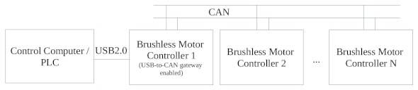
The controllers feature a built-in USB-to-CAN routing function, a “built-in USB2CAN adapter/dongle”, that enables PCs/PLCs to access an entire CAN network through connection to a single SERVOSILA controller via its USB port. In other words, by connecting to a USB port of a single SERVOSILA controller, a control computer/PLC gains access to the entire CAN network to which the SERVOSILA controller is connected to. Up to 16 controllers chained via their CAN ports can be controlled by the same PC/PLC using the built-in USB-to-CAN routing function. The limit is mainly due to throughput of a USB port of the SERVOSILA controller that acts as a USB2CAN dongle in addition to driving a motor; otherwise, all devices on a CAN network are equally accessible to a control computer/PLC via a connection to a single SERVOSILA controller. This includes non-Servosila devices such as GPS receivers or IMUs.
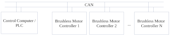
Up to 126 Servosila controllers can be connected to the same CAN bus instance if a control computer/PLC has a hardware CAN interface. Linux SocketCAN API can be used to develop software that sends commands to SERVOSILA controllers or receives telemetry back from the controllers.
Many off-the-shelf software products such as LabView support SocketCAN API out of the box, and come with an integrated CANopen stack. If the path taken is to develop the control software from scratch, there are many samples of open source programs available on the Internet that make use of Linux SocketCAN API.

Whenever a USB 2.0 interface (vs. a CAN interface) is used to connect SERVOSILA controllers to a Linux or a Windows 11/10/8 computer, the controllers appear as Virtual COM ports to both operating systems. A semi-standard text protocol called SLCAN is then used to send commands to the controllers through the virtual COM port as well as for receiving telemetry back.

In addition, most Linux distributions come with a special SLCANd daemon which makes SERVOSILA controllers attached via USB Virtual COM ports appear as CAN devices or as USB2CAN dongles. This daemon makes it possible to use the same Linux SocketCAN API whenever the SERVOSILA controllers are connected to Linux via USB 2.0 or a CAN bus interface (does not matter which one, the API is still SocketCAN API).
As Windows 11/10/8 systems do not have such a unified CAN bus API, the ways for a control system’s software running on Windows to interact with SERVOSILA controllers include:
- either through a virtual COM-port (USB 2.0) by writing to and reading from the port using a standard text protocol called SLCAN which is based on exchange of text strings formatted according to fairly simple open specification,
- or using a third-party USB2CAN adapter/dongle, and whatever programming API the adapter/dongle provides for Windows.
In general, user software for a control computer/PLC can be developed in any language that supports either Linux SocketCAN API or read/write operations for virtual COM ports on Windows 11/10/8 or Linux. This includes C/C++, Qt, Java, Python, MATLAB, LabView, and many other languages and packages.
Servoscope
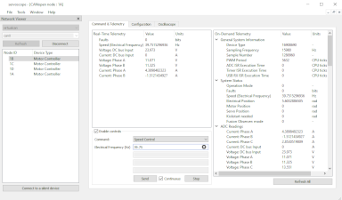
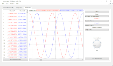
The SC-series controllers come with a graphical software tool called Servoscope. The tool provides means of configuring the controllers, displaying real-time telemetry coming via CAN bus or USB, and sending commands down to the controllers.
The tool allows visualizing the telemetry data by plotting graphical charts. This is helpful when tracking down transient issues with electric drives.
The application runs on Windows 11/10/8 or Linux including the popular distributions of Debian and Linux. No drivers need to be installed on either of the platforms to run the tool. The tool connects to SERVOSILA controllers via CAN bus or USB interfaces.
Electric Motor Simulator
Servoscope comes with a built-in software simulator of electric motors. In a real time, the simulator numerically solves differential equations that define the dynamics of brushless motors, and provides a simulated CAN/CANopen interface via Linux SocketCAN API for user control software being tested to connect to. The interface of the software simulator exactly matches the interface of a real SC-series controller coupled with a real electric drive.
The simulator allows debugging of user software via CAN/CANopen protocol prior to procuring a real hardware. Even if the hardware is available, it is still wise to first test your code against a simulator to avoid risking to burn a motor, break a gearbox, or cause an injury.
The simulator allows modeling the behavior of brushless motors or control systems under various conditions including dangerous or critical ones. The simulator is one of the software tools packaged into Servoscope application.
Specifications
| Parameter | Value | |
|---|---|---|
| Supported types of electric motors |
Brushless DC Motors (PMSM, BLDC, Direct Drive, Gimbal), both Sensored or Sensorless. Brushed Motors (Full support including ESC and Servo modes). Solenoids. |
|
| Number of simultaneously connected motors: | 1 brushless motor, or 1 brushed motors or solenoid |
|
| Nominal Current |
SC-60: 32Arms or 45A phase-to-phase amplitude, SC-25: 17Arms or 25A phase-to-phase amplitude |
|
| Input voltage | 6-60 V DC | |
| Operation modes | Electronic Torque Control (ETC), Electronic Speed Control (ESC), Servo Control, Direct Drive Control. Brake, Starter-Generator, System Identification |
|
| Supported algorithms of brushless motor control | Field-Oriented Control (FOC), EMF Observer, Hall Sensors Observer, D-Q axis Coupling Compensation, Field Weakening, Fault Management, Motor Dynamics Management |
|
| Auto configuration (system identification) function | Yes | |
| Interfaces to absolute position encoders | BISS-C, SSI, SPI, PWM, Quadrature with Index Signal |
|
| Max. resolution of encoder | 32bit | |
| Built-in network router | USB-to-CAN router («USB2CAN dongle») 11bit and 29bit identifiers are supported |
|
| Control Interfaces |
CAN bus with CANopen application protocol; USB 2.0, a virtual COM port, with SLCAN application protocol; PWM to RC Receivers, PLCs or Autopilots |
|
| CAN bus Terminal Resistor 120 Ohm | Yes (jumper controlled) | |
| Supported CAN bus bit rates | 1 mbit/sec 500 kbit/sec 250 kbit/sec 125 kbit/sec 100 kbit/sec 50 kbit/sec | |
| CAN bus ports | 2 (parallell) | |
| USB 2.0 ports | 1 | |
| GPIO functions | 2x Limit Switch inputs 1x Emergency Stop input 1x dedicated GPIO output (discrete or PWM signal) 1x dedicated GPIO input (discrete) |
|
| Supported operating systems |
Windows 11, 10 (no driver is needed) Windows 8, 7 (driver is provided) Linux (no driver is needed) including Debian, Ubuntu, Raspberry PI OS |
|
| Programming APIs |
CAN/CANopen, Linux SocketCAN API, USB SLCAN protocol via a virtual COM-port (USB2.0) for Windows 11,10,8 and Linux, G-code, DLL API for Python, C++, C#, etc |
|
| Software Servo Actuator Simulator | Yes | |
| Power consumption when idling | 80-120 mA | |
| Dimensions |
SC-60R and SC-25R: 68mm x 40mm x 16mm SC-60C: outer diameter 60mm, height 16mm, inner diameter 24mm SC-25C: outer diameter 62mm, height 16mm |
|
| Weight | ~23g |
- Specifications
- Internet Shop
- Datasheet SC-60 [PDF]
- Datasheet SC-25 [PDF]
- SC-series Device Reference [PDF] [HTML]
- SC-series Programming Guide [PDF]
- SC-series C++ Sample Projects [ZIP]
- SC-series CANopen Electronic Datasheet [EDS]
- CAD files: SC-60R
- CAD files: SC-60C
- CAD files: SC-25R
- CAD files: SC-25C
- SC-25 Product Brochure [PDF]
- Harmonic Reducers
- YouTube
- Telegram